An overview of the anhedral tail design configuration of the Hawk Aircraft.
Aircraft
Hawk BAE
Role
Advanced Trainer Aircraft
Origin
United Kingdom
Users
Military
Crew
2
Manufacturer
BAE Systems
MTOW
9100 kg
Wing Area
16.70m2
Wingspan
9.94 m
Height
3.98 m
Range
2520km
T/W ratio
0.65
Max Speed
0.84Mach
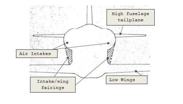
The initial concept of the hawk aircraft had a frontal cross-section without the intake fairings, shown in Figure 1. The air intakes and the tailplane were placed high and had a low-wing configuration. This gave rise to an inherent issue leading to an aerodynamic profiling problem between the air intake and the wing root.
Figure 1 - Initial design concept of the Hawk Aircraft | Credits - Harry Fraser-Mitchell, aerosociety.com | garudauniverse.com
At a low Mach number, a strong vortex is developed on the upper surface of the intake. The local supersonic speed generates shock waves when coupled with the vortex and interferes with the tail. It is placed on a slightly higher plane than the wing due to which separation occurs at the shock front. Due to this, the under-surface of the horizontal stabilizer/tail suffers problems in the pitching moment arising due to non-linear variation in the pitching moment coefficient(Cm). It also has a large area with low dynamic pressure.
By reducing the tailplane height, the stability issue may increase, interpreted from the Cm vs Angle of incidence plot from the testing phase results. The effect was observed more with the low-tail plane and anhedral-tail plane configurations. The loss of stability begins at very low incidence angles (~2-3°) for low anhedral tailplanes at higher Mach number (Mach ~0.8).
On the other hand, a high tailplane configuration results in pitching moment variations at higher incidence angles (~7°). The flow around this angle of incidence deteriorated drastically on the under-surface for a low anhedral tailplane configuration. The flow separation was observed to be less affected.
The solution, here, was to fill the gap between the air intake and the wing root where the anhedral tailplane showed the best results. The modified fuselage resulted in an anhedral tailplane that gave almost no severe changes in the pitching moment coefficient, thus providing the best stability out of all the configurations.
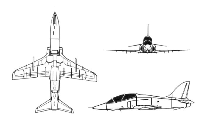
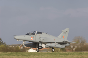
Hawk Aircraft Final Design | Credits - fas.org | garudauniverse.com
Instead of filling the gap, the air intake was lowered to sit just above the wing and was modified to maintain the sweep between the wing root and the fuselage. The fuselage was lowered down “to a more favorable position” at the rear section, in conjunction with an anhedral tailplane. This alleviated some of the high-speed problems arising due to the placement of air intakes, wing, and tailplane initial configuration.
The idea was to place the tailplane as low as possible and most likely to place it under the tailpipe nozzle. But structurally, it was difficult to support the tailplane.
Apart from providing stability in the case of the Hawk, the anhedral tails provide a way to escape from the downwash of the wing at high angles of attack, thus, helping in decreasing the stall speed, and may assist in the install-recovery. In propeller aircraft, the anhedral tailplane may also be useful in getting the tail to clear off the “prop wash”.
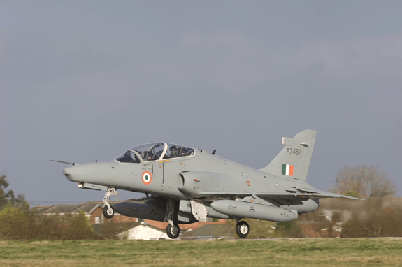
Illustration of Hawk Aircraft | Credits - HAL | garudauniverse.com
Credits – The Hawk Story, Journal of Aeronautical History
* The information provided herein is, to the best of our knowledge and is only for informative purpose. If you have a news update or correction, let us know at -info@garudauniverse.com
We use cookies to ensure that we give you the best experience on our website. If you continue to use this site we will assume that you are happy with it.OkNoPrivacy policy